Saturday, 16 October 2010

Part 5 - UVW Mapping

UVW Mapping is the first stage of the texturing process that will be used on the model, it allows the model to be 'flattened-out' into a 2d map grid, where the texture will later be painted onto in photoshop.


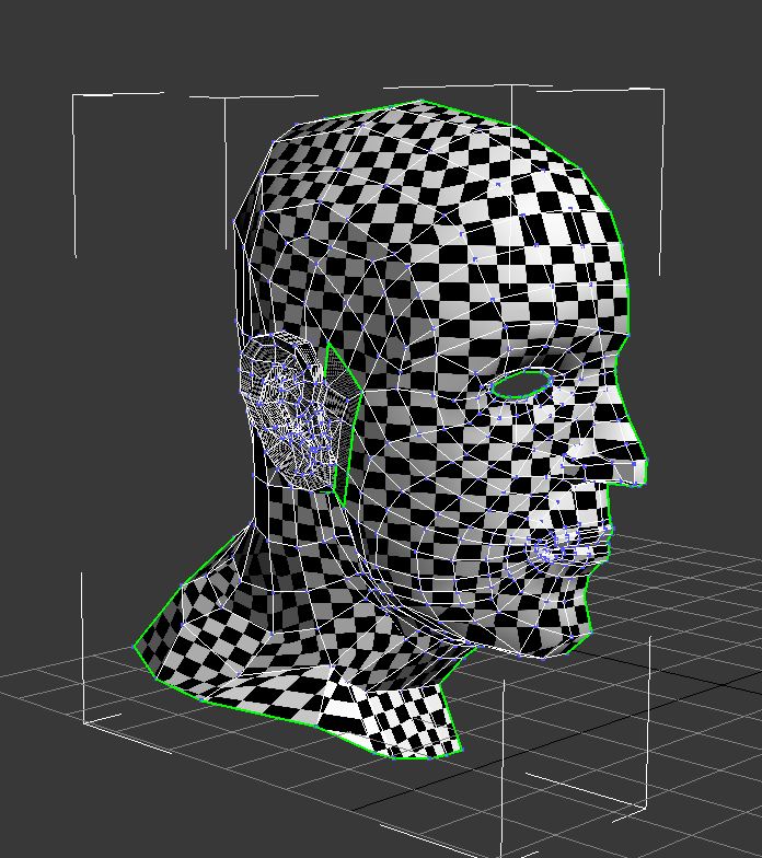
To begin, a simple checkered pattern material is apply to the model, which tells us how smoothly the flow of polygons is across the geometry of the head.

The area that will be worked on first is the majority of the head and face - the ear is a complex design and is best suited to being UVW mapped seperately. In order to create an accurate UVW coordinate map, a suitable projection method needs to be used. In this case the 'cylindrical' tool is used to correctly map the UVW coordinates, bearing in map that only half of the model will be UVW mapped to begin with. Its important here to ensure the cylindrical gizmo is scaled and centered to ensure no 'seams' are present on the UVW map (this also prevents problems when the texture is mirrored on both sides of the face later.


To continue, the UVW map can now be perfected in the editor window.

Hot Tip - make sure 'constant update' is enabled in the options panel of the edit UVWs box. This allows you to see what effect moving the vertices around here has on your model.

First, I needed to ensure the texture coords have been imported properly - this is done by selecting 'inverted faces' under the select tab. To begin with the majority of the faces are inverted, however this can be solved by mirroring the UVW map, followed by correctional positioning and scaling.

One of the most noticeable problems with the uvw map is stretching. The top of the head is the best example, but this can be fixed by 'relaxing' the vertices using the relax tool, which rounds out the geometry. This same process needs to be repeated on areas around the head with significant stretching of the quads.


The second issue resulting from the use of uvw mapping is 'overlapping'. There will be some areas such as the eye which contain a large number of vertices overlapping, creating a messy web effect.

To solve this, I used the 'paint-select mode' to highlight the problem vertices and those directly next to them (surrounding the eye only) and used the 'relax by centers' tool to seperate and organise them effectively. To finish, I also extended the inner loop of the eye by scaling it up to even out the eye socket.


A final check at this point is to ensure there are no more overlapping or inverted faces present on the uvw map. The end result can be seen below, there is a nice smooth flow of polygons across the model.

Friday, 15 October 2010

Part 4 - Creating The Ear

The ear is a fairly complex structure, with many areas of advanced geometry so to create this, the same process that was used to craft the face will be repeated here..

Using the 'Line' tool, quads were drawn to cover the entire area, which makes up the ear with a small section to the right which connects to the head - this will allow us to attach the ear more easily later.


Following this, the ear is then extending outwards to begin forming its 3d shape using the front viewport and reference image.

To add further detail to the ear geometry such as the definitive ridges on the inside of the ear, the 'chamfer' tool allows you to create a border in the interior of the polygon - thus allowing better detail to be created.

However, using this feature can create messy corners, resulting in triangles (as the screenshot shows), which is bad practice. To resolve this issue, the edge at the base of the triangles are selected and 'collapsed', again using the collapse tool.

This removes the unwanted triangles and produces a clean set of polygons to work with.

The result from using the chamfer tool can be seen significantly when a turbosmooth modifier is applied to the ear as these images below show. I am very pleased with the result so far!


Hot Tip - its important not to rush this stage as messy modelling can result in a very poor quality model. Experimenting with different vertice position and chamfer settings provides a great deal of flexibility.

Wednesday, 13 October 2010

Part 3 Continued - Extending the Neck


The next stage is to continue extending the head and neck region to complete the structure of the model. Extending the neck and jaw line can be done by selecting an edge next to the area you wish to create a new polygon and holding shift to 'drag' a new polygon.

Its important here to studying the geometry of how the neck curves and dips inwards to form the jaw line and start of the neck. Using the left and perspective viewports here allow accurate positioning of the vertices, however it takes a fair period of time to be a nice smooth curve forming the neck areas.

Friday, 8 October 2010

Part 3 - Creating the Head

Now the face is complete, I can begin modelling the rest of the head. The best way to begin here is to create a sphere in the left viewport and rotate the shape 90 degrees using the angle snap tool, then scaling the sphere to roughly fit the shape of the head.

The reason behind rotating the sphere, is to avoid using the center point (where all the vertices meet), due to the huge amount of triangles that surround this area!
Now we need to do some hacking on the sphere to get the polygons that we will be using to form the shape of the head - this was done using the 'brush selection' tool while under the polygon mode in the editable poly to highlight what areas of the sphere are not required and deleted.

The only sections of the sphere that will be used in the uppermost polygons. Notice that the center-point polygons are also removed for obvious reasons, leaving us with a clean shape to work with.

Hot Tip - Its a great opportunity here to reduce the amount of polygons compromising the model by selecting every other row of polygons, then using the 'Collapse' tool under edit geometry.. This helps to simplify the model by reducing the number of polygons consisting of the curve forming the back and top of the head.


To join the head and face together, the 'snap' tool is perfect. This allows you to 'semi-weld' the vertices of one shape to the other, providing an accurate shape to later join together as the vertices from one shape cannot be welded to those from another shape if they are not part of the same element.

The empty sections of the head are filled by simply creating new polygons, most-preferably by selecting an edge and holding the shift key to drag a new polygon out, followed by the vertices being welded together.

The model so far compromises of the face and a roughly modelled head section which will later be perfected to create a more realistic curve and structure.

Tuesday, 5 October 2010

Part 2 - Facial Detail

Following on from creating the face outline, the next stage is to start adding some detail to areas of interest such as the nose, mouth and eye..

The Eye
The eye is a very complex area to model, as there are details with fine detailing and to get a natural look, careful adjustments to the shape of the vertices are needed.


Again using the perspective view here, helps when trying to get the shape of the eye socket correct as well as adding detail such as the eye lids, which was created by using the extrude tool on the inner most edges of the eye.

Hot Tip - adding a 'turboSmooth' modifer to the existing model allows you to see more clearly how the vertices you are working on are effecting the face's appearance.

The Mouth
The mouth was fairly straight forward to create, extra lines of polygons were created to craft the shape of the lips. The overall shape of the mouth was tricky however as certain areas around the cheeks was in danger of being stretched, producing a very messy model!


The Nose
The nose plays an important role in how the structure of the face is formed, it is difficult to keep the shape of the nose balanced in comparison to the face (too big or pointy noses change the appearance dramatically!).

The perspective view, allows you to see how the nose is forming and its size etc. in comparison to the face, careful amendments in the left view allows you to create fairly accurate shape and detailing, such as how the nostrals dip inwards and curve.


To finish, the side of the face was further extended to begin wrapping around the head. A 'symmetry' modifier was also added here to complete the face, this saves a huge amount of time by mirroring the one side you have created on the other side.


Monday, 4 October 2010

Part 1 - Face Creation


The first stage of development was to begin crafting the shape of the face, this was done using the 'Line' tool under the create panel. The line tool allows you to draw polygons or 'Quads' individually - which in this case, allowed me to follow the shape and contours on the reference image. This was used to cover the entire surface of the face.

At this stage, it was obvious that one of my reference images was slightly misshapen, resulting in alignment problems. A temporary solution to this was to re-scale the image in 3ds max in an attempt to offer a more accurate image to work with.

The next step is to give the model a '3D Look'. Before this can be done, the model has to be converted to an 'editable poly' which can be found in the modifier list. Doing this provides greater flexibility when working with complex shapes such as faces!

The process of extending the face using the reference images was done by customizing the viewports in 3ds max, showing the front and left views only. As you can see from the screenshot, the vertices on the inside of the face are 'dragged' towards the outline of the face in the left viewport - forming the face structure. This step was repeated for all vertices, working in a pattern from inside to outside.

Hot Tip - It's very useful switching over to the perspective view to see how the shape of the face is coming along, here you can make adjustments to the position of the vertices as and when needed.

The End Result...


Friday, 1 October 2010

Setting up 3DS Max.


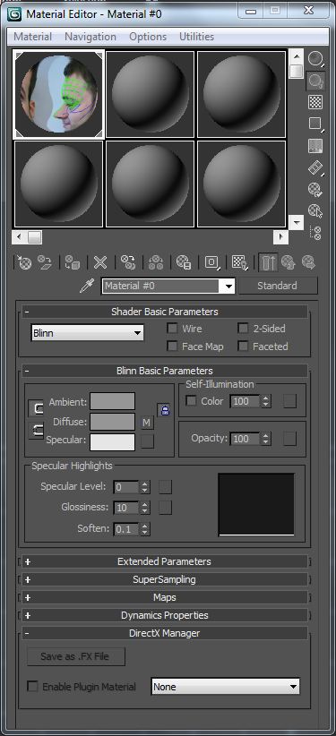
Now the Reference image is finished, it's time to import the photoshop .psd file in max using the material editor..

To use the images in 3ds max, we need to create two 'planes', one for the front image view and the other for the side image view of the head. To begin, a plane was created in the front viewport which will display the front face image..


The reference image is then added to the plane via the material editor. Unfortunetly the plane is not the correct size to display the reference image properly. To solve this I used the 'UVW Map' Modifier on the plane, followed by the 'Bitmap Fit' utility (This resizes the plane to the correct dimensions of the image being used).


Once the planes have been created the reference image was displayed on them by assigning the image as a material through the material editor. With some adjustments and positioning, the reference images are now ready to be used for modelling.