Friday 22 October 2010

Final Model & SWOT Analysis


Strengths:

This module has given me an insight into how professional looking models are created and what to expect when attempting to create a highly detailed piece of work.

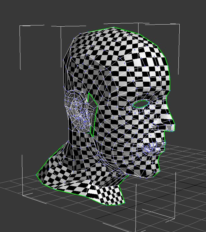
I feel I have gained a good understanding of how details of the face can be created through both modelling and texturing as well as how bump and specular maps can be used to further improve the realisticness of the skin.

Without the ability to look at how skin tones and bone structure play an important role in the geometry of the human head would not have been able to produce the work I have managed to.

Weaknesses:

One of the major problems I had with this task is the fact that one of the reference images used was not the wrong size or scale. This caused problems at different intervals but I was fortunetly able to work around this by sticking to the image that was the correct dimensions and scale.

Opportunites:

Previous experience with modelling in 3ds max, texturing and uvw Mapping have really helped me during this task. The opportunity to follow a professional artisit's tutorials in this module has allowed me to use different features in 3ds max that was previously unknown and not used. The tutorials have also given me an insight on how a task such as this should be done and what things to look out for such as polygon shapes and position.

Finally, I have been able to learn more about the structure of the human face and how skin is wrapped around bones as well as blending techniques in photoshop.

Threats:

I have been fortunate enough to not experience any more problems when undertaking this task, appart from the incorrect reference image - I will need to ensure that the images are setup correctly and are the correct dimensions before starting any future work like this.

Part 8 - Specular Map

To further improve the realisticness of the texture map on my head model, I have also added a specular map..

The specular map is used to highlight areas on the face which pick up the most light and help to pinpoint areas usually shaded, which is lost in the standard form on texturing.


This is created by painting white over the areas which are likely to be highlighted from natural light in the environment. Then a Gaussian blur filter is applied with a setting of about 5.0, which dramatically fades the white painted areas.

The texture map is then added to the model in 3ds max using the specular option in the material editor. The result can be seen below..

Part 7 - Bump Map

A bump map is used to create a more natural looking skin effect, producing bumps and creases in the skin in desires locations..


To create the bump map, the texture image was first 'De-saturated' to remove all colouring. This is followed by adding a 'High Pass' filter effect, which removes a majority of the shading on the image and highlights the creases and imperfections of the skin.


As you can see from the screenshots above, the bump map increases the realisticness of the skin and features.

Wednesday 20 October 2010

Part 6 - Texturing

The texturing process is done in photoshop and will make use of the reference images once again by taking sections of the images and painting them onto the texture map.

The texture map is first loaded into photoshop, and assigned as the background image . A new layer called 'Guide' is then added with a bright colour that stands out so it can be distinguished easily from any texture painting.

The background wireframe image is then pasted onto the guide layer via the 'quick mask' mode, which will only display the wireframe.

Texture painting is done by simply selecting areas on the reference image using the 'lasso' tool and pasting them onto the wireframe image (on a new layer of course!).

This process is repeated until large sections of the face have been added. At this point, there are alot of open gaps between the different sections which need to be filled in. I did this by using the 'patch' and 'clone stamp' tools to drag smaller sections of the images in to fill any gaps and blend the skin layers.


The texture needs to be applied to the model in 3ds max, in order to see how the texture is being applied, and to find any problems. Using the material editor, the photoshop file is imported and applied to the model. The screenshots below show different stages of the texture mapping development..


The finished texture map..


Note - I have mirrored the image across to the other side, this saves time and allows the texture map to cover the entire model.

Monday 18 October 2010

Part 5 Continued - UVW Mapping The Ear

Its now time to apply the uvw mapping to the ear.

To start, the polygons that were not selected, which consisted of the rest of the head, will be used for the ear's uvw map.


Previously I used the cylindrical method to map the uvw coordinates - however for this type of uv mapping, the 'pelt' tool provides a much better result, allowing you to define the dominant direction of the ear (in this case - the left view).

Hot Tip - remember to add a suitably placed seam to the ear, this allows the image to be flattened more effectively.

Next the pelt editor is used to flatten the ploygons. The 'stretch ring' was first edited to simulate a pulling effect on the vertices, which starts to flatten the image. This is done by using the relax tool alongside the pelt tool.


The ear then needs to be positioned seperately from the main head mapping, to reduce the chance of texture overlapping when I apply the texture to the model. The ear map also needs to be scaled correctly to ensure a nice fit in the hole in the head map. The easiest way to do this was to move the ear map over the gap and adjust the vertices as necessary.


After doing this, the flow of polygons around the ear can be clearly seen, a nice smooth flow which is perfect for texturing!


Finally, before any texturing can be started, the head and ear mapping needs to be mirrored in the UVW map editor, which will cover the other side of the head. This also allows us to paint the texture on both sides of the model. The most important step here is to align and weld the two maps together correctly to prevent any ripping in the texture.


The final UVW map which will be used in photoshop to paint the textures onto.


Saturday 16 October 2010

Part 5 - UVW Mapping

UVW Mapping is the first stage of the texturing process that will be used on the model, it allows the model to be 'flattened-out' into a 2d map grid, where the texture will later be painted onto in photoshop.


To begin, a simple checkered pattern material is apply to the model, which tells us how smoothly the flow of polygons is across the geometry of the head.

The area that will be worked on first is the majority of the head and face - the ear is a complex design and is best suited to being UVW mapped seperately. In order to create an accurate UVW coordinate map, a suitable projection method needs to be used. In this case the 'cylindrical' tool is used to correctly map the UVW coordinates, bearing in map that only half of the model will be UVW mapped to begin with. Its important here to ensure the cylindrical gizmo is scaled and centered to ensure no 'seams' are present on the UVW map (this also prevents problems when the texture is mirrored on both sides of the face later.


To continue, the UVW map can now be perfected in the editor window.

Hot Tip - make sure 'constant update' is enabled in the options panel of the edit UVWs box. This allows you to see what effect moving the vertices around here has on your model.

First, I needed to ensure the texture coords have been imported properly - this is done by selecting 'inverted faces' under the select tab. To begin with the majority of the faces are inverted, however this can be solved by mirroring the UVW map, followed by correctional positioning and scaling.

One of the most noticeable problems with the uvw map is stretching. The top of the head is the best example, but this can be fixed by 'relaxing' the vertices using the relax tool, which rounds out the geometry. This same process needs to be repeated on areas around the head with significant stretching of the quads.


The second issue resulting from the use of uvw mapping is 'overlapping'. There will be some areas such as the eye which contain a large number of vertices overlapping, creating a messy web effect.

To solve this, I used the 'paint-select mode' to highlight the problem vertices and those directly next to them (surrounding the eye only) and used the 'relax by centers' tool to seperate and organise them effectively. To finish, I also extended the inner loop of the eye by scaling it up to even out the eye socket.


A final check at this point is to ensure there are no more overlapping or inverted faces present on the uvw map. The end result can be seen below, there is a nice smooth flow of polygons across the model.


Friday 15 October 2010

Part 4 - Creating The Ear

The ear is a fairly complex structure, with many areas of advanced geometry so to create this, the same process that was used to craft the face will be repeated here..

Using the 'Line' tool, quads were drawn to cover the entire area, which makes up the ear with a small section to the right which connects to the head - this will allow us to attach the ear more easily later.


Following this, the ear is then extending outwards to begin forming its 3d shape using the front viewport and reference image.

To add further detail to the ear geometry such as the definitive ridges on the inside of the ear, the 'chamfer' tool allows you to create a border in the interior of the polygon - thus allowing better detail to be created.

However, using this feature can create messy corners, resulting in triangles (as the screenshot shows), which is bad practice. To resolve this issue, the edge at the base of the triangles are selected and 'collapsed', again using the collapse tool.

This removes the unwanted triangles and produces a clean set of polygons to work with.

The result from using the chamfer tool can be seen significantly when a turbosmooth modifier is applied to the ear as these images below show. I am very pleased with the result so far!


Hot Tip - its important not to rush this stage as messy modelling can result in a very poor quality model. Experimenting with different vertice position and chamfer settings provides a great deal of flexibility.